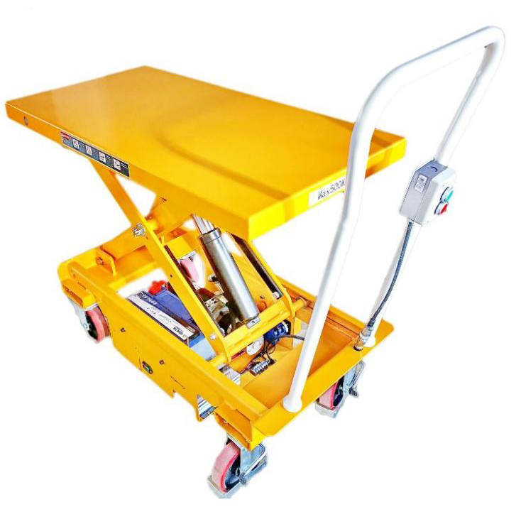
ES50D-Instruction Manual ELECTRIC LIFT TABLE
ELECTRIC LIFT TABLE
Instruction Manual
READ THIS OPERATION MANUAL COMPLETELY BEFORE USING.THOROUGHLY UNDERSTAND AND FOLLOW ALL SAFETY INSTRUCTIONS.IF THIS IS LOST, PLEASE CONTACT YOUR LOCAL SUPPLIER FOR A NEW COPY.IF THE WARNING/CAUTION DECAL ON THE UNIT IS LOST, PLEASE CONTACT YOUR LOCAL SUPPLIER FOR A NEW COPY.
Note: On this manual, WARNING means the danger which can lead death or serious injury. CAUTION means the danger which can lead slight injury or property damage.
1. WARNING
1. DO NOT allow another person to stand in front of or behind lifter when it starts to move.
2. ALWAYS travel with table in lowered position. Load could fall down.
3. NEVER sit, stand or ride on platform. SEVERE PERSONAL INJURY could result.
4. NEVER go under platform. SEVERE PERSONAL INJURY or DEATH could result.
5. DO NOT use in area of multilevel floor surface that could create loss control and result in SEVERE INJURY and PROPERTY DAMAGE.
6. DO NOT use lifter on slope, unlevel or soft surface. Lifter may become uncontrollable. SEVERE PERSONAL INJURY and PROPERTY DAMAGE could result.
7. KEEP FEET CLEAR of rolling wheels that could result in SEVERE PERSONAL INJURY.
8. DO NOT load one fork more than the other and DO NOT load tips on forks. SEVERE PERSONAL INJURY and PROPERTY DAMAGE could result.
9. DO NOT overload lifter .ALWAYS stay within designated capacity and load center rating. SEVERE PERSONAL INJURY and PROPERTY DAMAGE could result.
10. SHEARING HAZARD. NEVER place hands or feet under lowering table. SEVERE PERSONAL INJURY could result.
11. NO FIRE during charging. Read battery operation manual.
12. HIGH VOLTAGE. Disconnect battery socket before opening control panel box.
13. DO NOT remove battery terminal cover. Short-circuit or electric shock could occur.
2. CAUTION
1.Hazard or unsafe practice which, if not avoided, may result in MINOR or MODERATE PERSONAL INJURY and PROPERTY DAMAGE.
2.READ THE OPERATION MANUAL COMPLETELY BEFORE USING AND THOROUGHLY UNDERSTAND AND FOLLOW ALL SAFETY INSTRUCTIONS.
3.This lifter is designed to use with stable uniform load on a solid lever floor. DO NOT use the lifter for any other purpose than its intended use.
4.Lifter shall be operated by TRAINED personnel only. OPERATOR shall read “Operation Manual”completely and thoroughly understand the controls and operation of this equipment BEFORE operating the lifter.
5.ALWAYS observe lifter and ALWAYS stay at the controls while the lifter is in motion, RELEASE controls and STOP lifter immediately if load on lifter appears to become unstable. NEVER leave the loaded lifter unattended unless the table is in the fully lowered position and the lifter is locked reliably.
6.DO NOT slid the load on or off the table. The lift may move allowing the load to fall. SEVERE PERSONAL INJURY and PROPERTY DAMAGE could result.
7.DO NOT use lifter with unstable, unbalanced or loosely stacked load. Unbalanced loads may become unstable and fall. SEVERE PERSONAL INJURY and PROPERTY DAMAGE could result.
8.ALL lifter service must be performed by qualified personnel only.
9.ALWAYS keep feet, hands and fingers away from casters, load wheels and all moving components. SEVERE INJURY could result.
10.ALWAYS perform maintenance and inspections with lifter unloaded.
11.Prolonged continous working might cause damage of power pack.
12.Stop operation if temperature of hydraulic oil is too high.
The lifter is NOT waterproof and is intended to be used in a dry environment.
NOTE
The table is equipped with an aluminum guard to avoid accidental danger.
If aluminum guard strikes an object while the table lowers, stop operation and check the lift table. After making sure no any abnormality, strike the UP button slightly and then the electric system will function as before.
3. DAILY INSPECTION
Daily inspection is effective to find the malfunction or faulty on the lifter. Check the lifter on the following points before the operation.
CAUTION |
DO NOT use lifter if any malfunction or faulty is found. |
(1)Check scratch, bending or crack on the lifter.
(2)Check smooth movement of the wheels.
(3)Check if there is oil leakage.
(4)Check vertical creep of table.
(5)Check the function of brake.
(6)Check if all the bolts and nuts are tightened firmly
4.NAME OF PARTS
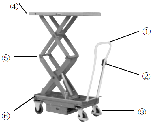
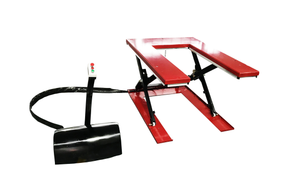
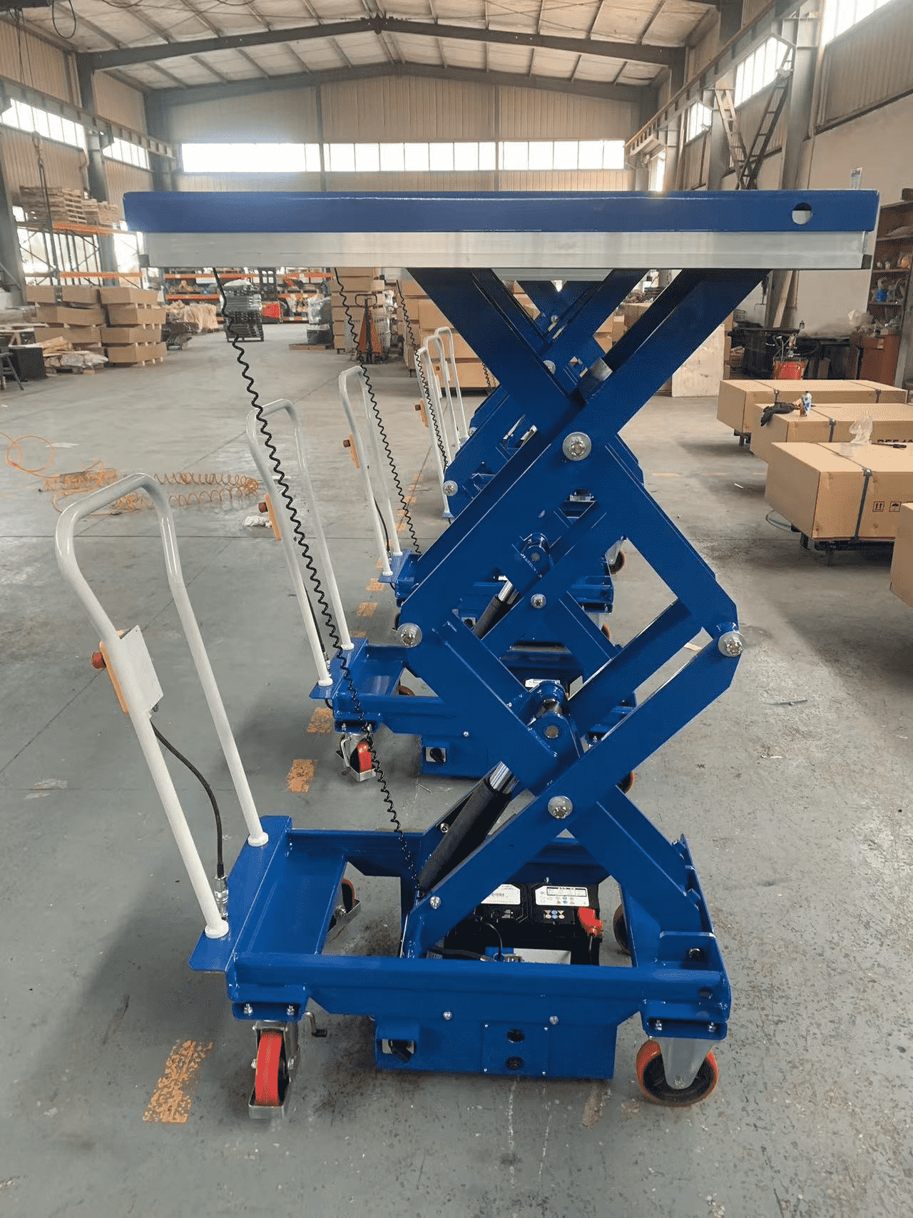
1.Handle | 4.Platform and aluminum guard |
2.Switch | 5. Link |
3.Brake Pedal | 6.Guide rail |
5. OPERATING LIFT TABLE
How to use thebrake.
CAUTION |
Brake lift table when not moving it in order to prevent sudden movement. |
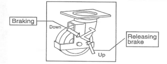
The brake is equipped with the swivel caster on the right side.
(1) Braking the wheel, press the brake pedal.
(2) Releasing the brake, lift up the brake pedal.
6. LIFTING UP FORKS
CAUTION |
1.DO NOT overload lifter. Stay within its rated capacity. 2.Prolonged continous working might cause damage of hydraulic power pack. 3.Step operation if temperature of hydraulic oil is too high. |
Push the button “UP”and the table lift up.

7.LOWERING TABLE
CAUTION |
DO NOT lower table with load too fast and stop suddenly. Impact load could be created and lifter could be damaged. |
Push the button DOWN and the table lower.
8.MOVING THE LIFTER
WARNING |
DO NOT move lifter on slope or inclined surface, otherwise lifter become uncontrollable and create danger. |
(1)Make the load stable to prevent it to fall.
(2)Lower the table down.
(3)Release the brake and move the lifter.
CAUTION |
KEEP watching the condition of load. Stop operating lifter if load become unstable. |
9.CHARGING THE BATTERY
(1)Check the quantity of Battery fluid. If it is insufficient, add the battery solution according to battery operation manual.
(2)Disconnect the battery socket.
(3)Connect the charging port of battery socket to the battery charger.
10.REGULAR INSPECTION
Perform the regular inspection for the safety operation.
(1)Check the items expressed in daily inspection (daily).
(2)Lubricate with grease the guides where roller moves. Also, lubricate the grease nipples. (Every month)
(3)Lubricate all the pivoting points and axles. (Every 6 months)
(4)Replace the hydraulic oil for the first time: Accumulated working ten hours’
(5)Replace the hydraulic oil. (Every 12 months)
11.TROUBLE SHOOTING
TROUBLE | CAUSE | REPAIR |
Platform do not rise while motor does not run. | 1.Faulty wiring. | 1.Check the wiring referring to the actual wiring diagram. |
2.Battery socket is disconnected | 2.Connect the battery socket. | |
3.Battery charge is insufficient. | 3.Charge the battery. | |
Platform do not rise while motor runs. | 1.Faulty adjustment of relief valve. | 1.Adjust relief valve again. |
2.Faulty hydraulic pump. | 2.Replace power pack. | |
3.Shortage of hydraulic oil. | 3.Add oil. | |
Vertical creep of table. | 1.Oil leakage in power pack. | 1.Replace lowering valve. |
2.Oil leakageform hydraulic circuit. | 2.Check hydraulic circuit and repair. | |
Oil leakage from cylinder. | Faulty sealing. | Replace sealing. |
Oil leakage from piping or joint. | Insufficient tightening or seal in valid. | Tighten joint again or Replace seal. |
Oil leakage from air breather. | Excessive quantity of oil. | Reduce oil quantity. |
12. SPECIFICATIONS
Model | ES50D | ||
Capacity (kg) | 500 | ||
Table (mm) | 520×1010 | ||
Min. table height (mm) | 495 | ||
Max. table height (mm) | 1618 | ||
Lifting stroke (mm) | 1123 | ||
Motor (KW) | 0.7 | ||
Work cycle of hydraulic power pack | 3 times of table moving up-down per 10 min. | ||
Approx. numbersof lifting at full charge and with full load.(times) | 40 | ||
Approx. time required to lift up table.(sec) | 15 | ||
Wheel (mm, diameter) | 150 | ||
Handle height(mm) | 1180 | ||
Weight (kg) | 198 | ||
13. HYDRAULIC CIRCUIT/WIRING DIAGRAM/ACTUAL WIRING DIAGRAM

ES50D
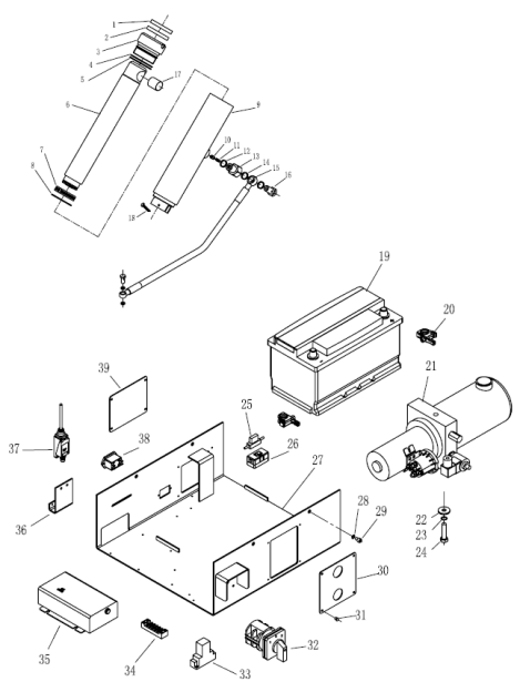

NO. | DESCRIPTION | Qty | NO. | DESCRIPTION | Qty |
1. | Seal cover DH50 | 1 | 54. | Roller for chassis | 2 |
2. | Y-ring UN50 | 1 | 55. | Bushing | 2 |
3. | Cylinder cover | 1 | 56. | Nut M10 | 2 |
4. | O-ring φ56×1.25 | 1 | 57. | washer 10 | 6 |
5. | O-ring φ56×3 | 1 | 58. | Safety rod | 2 |
6. | Piston rod | 1 | 59. | ScrewM10x40 | 2 |
7. | Piston ring | 1 | 60. | Grease cup M6 | 4 |
8. | Retaining ring | 1 | 61. | Pin axle | 3 |
9. | Cylinder | 1 | 62. | Internal scissors for chassis | 1 |
10. | Prevent burst valve | 1 | 63. | External scissors for chassis | 1 |
11. | Spring | 1 | 64. | Spring pin | 2 |
12. | Seal ring 18 | 1 | 65. | Nut M16x1.5 | 5 |
13. | Prevent burst joint | 1 | 66. | Split Pinφ3.2x26 | 5 |
14. | Seal ring 14 | 4 | 67. | Washer | 5 |
15. | High pressure hose | 1 | 68. | Bushing φ30xφ35x30 | 2 |
16. | Joint | 2 | 69. | Pin axle | 2 |
17. | Bushing φ25xφ28x40 | 1 | 70. | Retaining ring for axle25 | 2 |
18. | Split Pinφ4x36 | 1 | 71. | Pin | 1 |
19. | Battery | 1 | 72. | Bushing φ25xφ28x40 | 8 |
20. | Batteryclamp | 1 | 73. | Pin | 1 |
21. | Hydraulic power pack | 1 | 74. | Bushing | 2 |
22. | Washer10 | 2 | 75. | screw M6x16 | 2 |
23. | Spring washer 10 | 2 | 76. | screw M8×16 | 8 |
24. | ScrewM10x25 | 2 | 77. | Internal scissors for table | 2 |
25. | Fast acting fuse 10A | 1 | 78 | Bushing | 2 |
26. | Fast acting fuse 150A | 1 | 79. | Roller for table | 2 |
27. | Battery case weldment | 1 | 80. | External scissors for table | 2 |
28. | Spring washer8 | 9 | 81. | Pin | 1 |
29. | ScrewM8x25 | 4 | 82. | Bushing | 2 |
30. | Covering plate | 1 | 83. | Safety frame | 2 |
31. | Screw M4×10 | 25 | 84. | Nut M8 | 4 |
32. | Switch | 1 | 85. | Buffer-board | 4 |
33. | Switch | 1 | 86. | Spring | 4 |
34. | Terminal block | 1 | 87 | Fixed-board | 4 |
35. | Charger | 1 | 88 | Connected-board | 4 |
36. | Joint board | 1 | 89. | Fixed-board | 4 |
37. | Lifting limit switch | 1 | 90 | Safety switch | 2 |
38. | Battery indicator | 1 | 91. | Safety frame | 2 |
39. | Covering plate | 1 | 92. | Table | 1 |
40. | Handle | 1 | |||
41. | Washer12 | 2 | |||
42. | Spring washer 12 | 2 | |||
43. | ScrewM12x30 | 2 | |||
44. | Plug | 1 | |||
45. | Control switch | 1 | |||
46. | Chassis | 1 | |||
47. | Rubber sleeve | 3 | |||
48. | Rear wheel | 2 | |||
49. | Front wheel | 2 | |||
50. | Nut M10 | 16 | |||
51. | Spring washer 10 | 16 | |||
52. | ScrewM10x25 | 16 | |||
53. | Retaining ring for axle20 | 6 |








Please first Loginlater ~