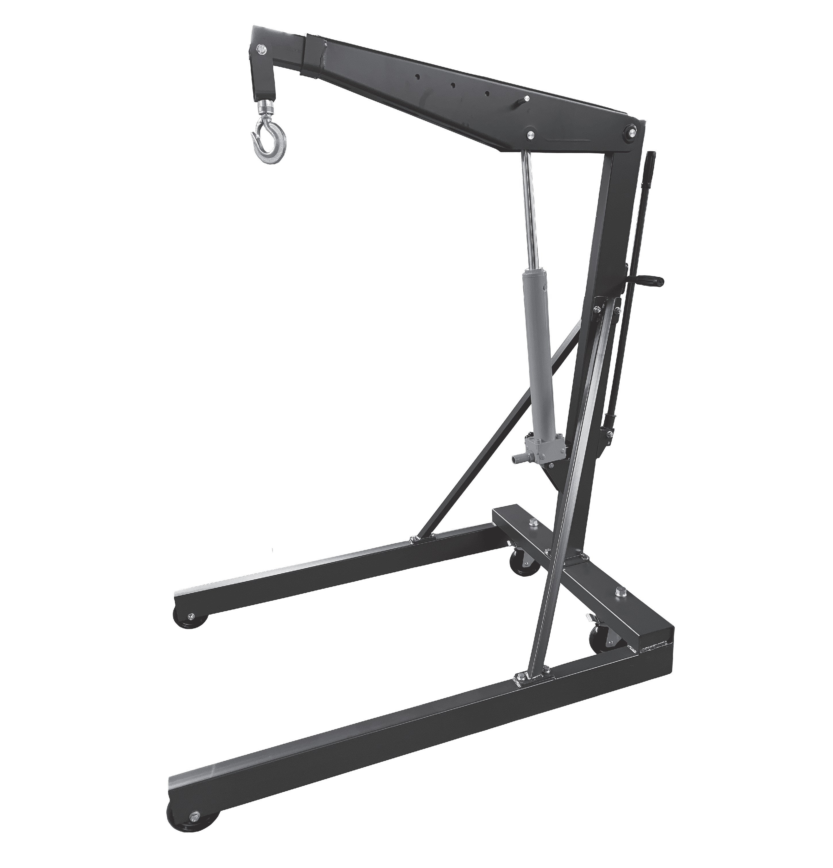
SA1000C-Instruction Manual Euro Shop Crane
Specifications
Model | SA500C | SA1000C |
Capacity (kg) | 500 | 1000 |
Base width(outside) (mm) | 950 | 950 |
Base width(inside) (mm) | 800 | 800 |
Max.Boom Length (mm) | 1360 | 1360 |
Min.Boom Length (mm) | 1060 | 1060 |
Max.Hook Height (mm) | 2150 | 2150 |
Min.Hook Height (mm) | 570 | 570 |
Net Weight (kg) | 81 | 103 |
Safety Instructions
1.Use cranes only on a firm level; never use on soft grounds.
2.The load to be lifted should never exceed the rated capacity.
3.Never operate the hydraulic power unit beyond its maximum stroke indicated on the label.
4.The capacity of the crane reduces as the jib extension is prolonged. Do not load the crane beyond the rated capacity for each specified jib extension position as indicated in the label.
5.The load hook is provided with a latching mechanism. Ensure it works properly.
6.To lift the load in a well balanced and stable way make sure the center of gravity remains always inside the crane base.
7.Never position any part of your body under the load.
8.Do not allow the load to swing or drop violently when moving.
9.The crane is not transportation device but in case the load has to be removed, lower the load and jib extension to the lowest possible point before transporting. The crane is not designed to sustain the load indefinitely, so when the operation is finished make sure the load is fully lowered and supported on a firm surface.
10.Make a visual inspection before each use the crane. Any crane which appears to be damaged must be removed from service.
11.As an additional safety feature the crane is equipped with a valve to prevent the unit from being overloaded. This unit must not be tampered with.
12.If these basic rules are not followed, injury to the user, the crane or the load being lifted may result.
Use and operation
1.Before using the crane, it is necessary to purge air from the valve system of the hydraulic unit.
2.This can be done by releasing the valve ,then pumping the hydraulic jack several times.
3.Raising the load, close the valve and pump the hydraulic unit. Any manipulation of the pressure relief valve is prohibited.
4.Lowering the load, release the valve slowly, the load can be lowered smoothly. Quick-releasing is strictly prohibited.
Maintenance
1.Lubricate all moving parts at regular intervals.
2.Always keep the crane clean and protected from aggressive conditions.
3.Check the oil level of the hydraulic unit with the piston fully retracted. Top up if necessary.
IMPORTANT : An excess of oil will render the crane inoperative.
4.Use only hydraulic oil, HL or HM types, with an ISO grade of cinematic viscosity of 30 cSt at 40ºC or an Engler viscosity of 3 at 50ºC.
VERY IMPORTANT : never use brake fluid.
5.When ordering spare parts, please state the part number as shown in the exploded view drawing provided, the model number and the capacity of the crane.
REPAIR
Both maintenance and repair must only be carried out by qualified personnel.
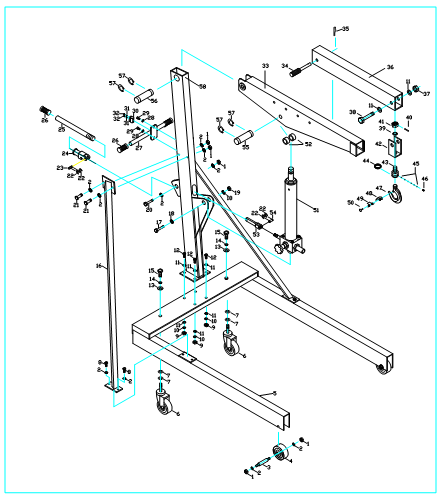
Parts List
No | Description | Qt’y | No | Description | Qt’y |
1 | Nut | 7 | 2 | Washer | 16 |
3 | Pin | 2 | 4 | Front wheel | 2 |
5 | Base | 1 | 6 | Steering wheel | 2 |
7 | Washer | 4 | 8 | Screw | 4 |
9 | Nut | 4 | 10 | Spring Washer | 4 |
11 | Washer | 10 | 12 | Screw | 4 |
13 | Washer | 2 | 14 | Spring Washer | 2 |
15 | Screw | 2 | 16 | Support | 2 |
17 | Screw | 1 | 18 | Washer | 2 |
19 | Nut | 1 | 20 | Screw | 1 |
21 | Screw | 2 | 22 | Snap ring | 4 |
23 | Pin | 1 | 24 | Socket | 1 |
25 | Jack handle | 1 | 26 | Hand grip | 3 |
27 | Handle | 1 | 28 | Washer | 2 |
29 | Screw | 2 | 30 | Spring seat | 1 |
31 | Washer | 2 | 32 | Screw | 2 |
33 | Boom | 1 | 34 | Pin | 1 |
35 | Spring pin | 1 | 36 | Lifting arm | 1 |
37 | Nut | 1 | 38 | Screw | 1 |
39 | Washer | 1 | 40 | Pin | 1 |
41 | Nut | 1 | 42 | Hook seat | 1 |
43 | Hook bolt | 1 | 44 | Spring | 1 |
45 | Ball | 12 | 46 | Screw | 1 |
47 | Hook | 1 | 48 | Latch | 1 |
49 | Spring | 1 | 50 | Pin | 1 |
51 | Ram assembly | 1 | 52 | Spacer | 2 |
53 | Linkage | 1 | 54 | Pin | 1 |
55 | Pin | 1 | 56 | Pin | 1 |
57 | Snap ring | 4 | 58 | Post | 1 |
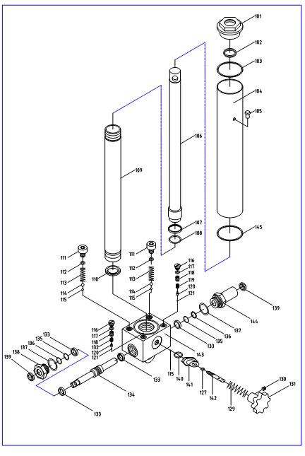
Parts List(Ram assembly)
No | Description | Qt’y | No | Description | Qt’y |
101 | Cylinder Head | 1 | 102* | O-Ring | 1 |
103* | Square-Ring | 2 | 104 | Reservoir | 1 |
105* | Oil Plug | 1 | 106 | Piston Rod | 1 |
107* | O-Ring Retaining | 1 | 108* | O-Ring | 1 |
109 | Cylinder | 1 | 110* | Washer | 1 |
111 | Screw | 2 | 112* | Washer | 2 |
113 | Spring | 2 | 114 | Ball | 2 |
115 | Ball | 3 | 116 | Screw | 2 |
117* | Washer | 2 | 118 | Screw | 2 |
119 | Spring | 1 | 120 | Seat | 2 |
121 | Ball | 2 | 127* | O-Ring | 1 |
129 | Spring | 1 | 130 | Screw | 1 |
131 | Release Knob | 1 | 132 | Spring | 1 |
133 | Y-Ring | 4 | 134 | Pump | 1 |
135 | O-Ring | 2 | 136 | Scraper Ring | 2 |
137 | O-Ring | 2 | 138 | Screw | 1 |
139 | Snap Ring | 2 | 140 | O-Ring | 1 |
141 | Screw | 1 | 142 | Release Indicator | 1 |
143 | Valve Block | 1 | 144 | Screw | 1 |
145 | Trapezoid | 2 | |||
*Included in the repair kit | |||||








Please first Loginlater ~