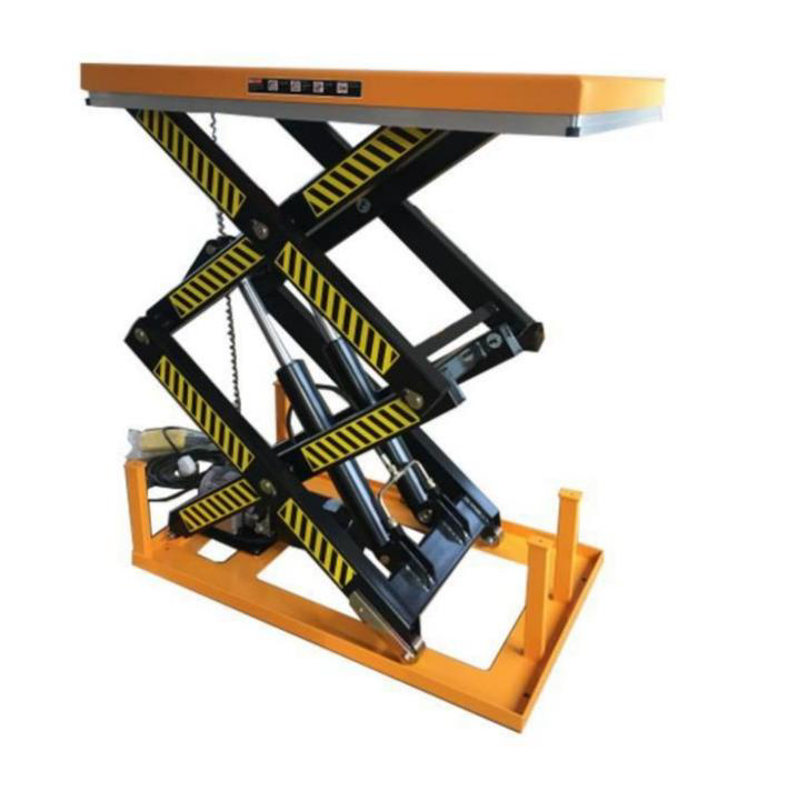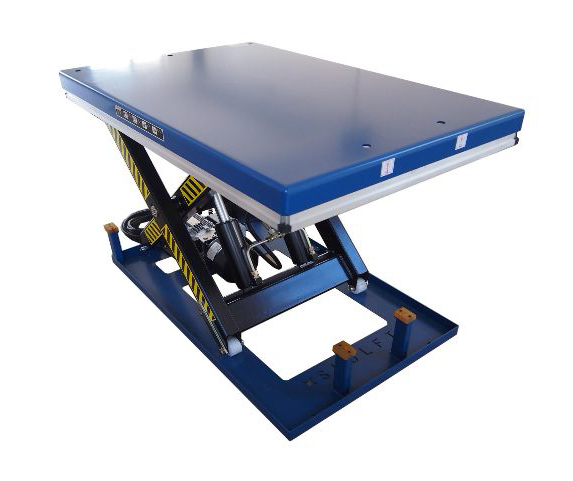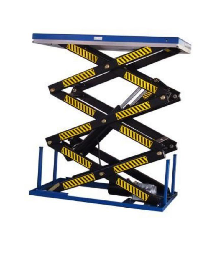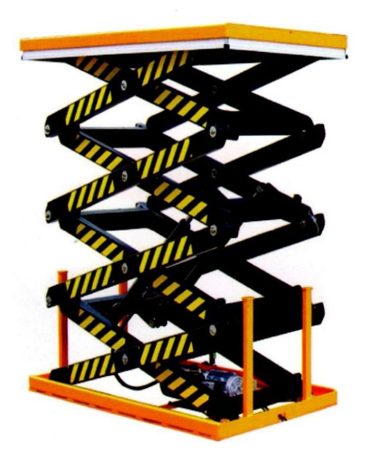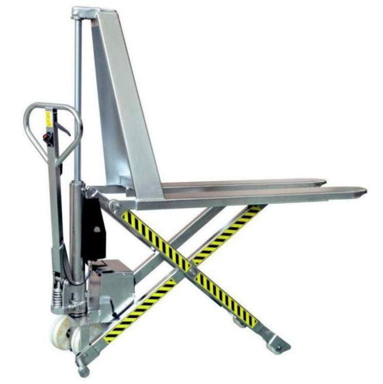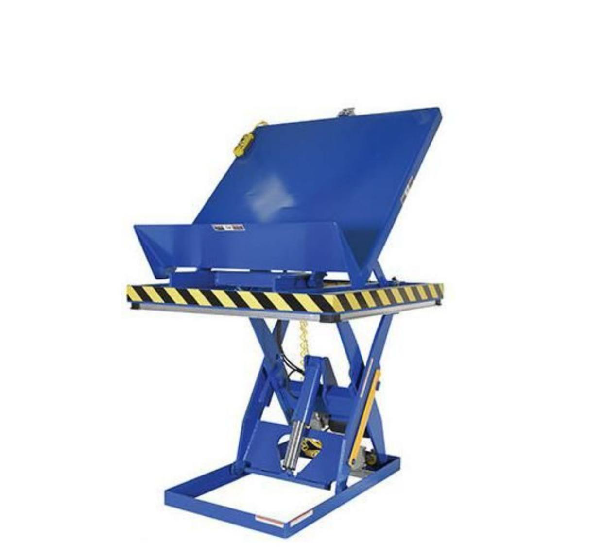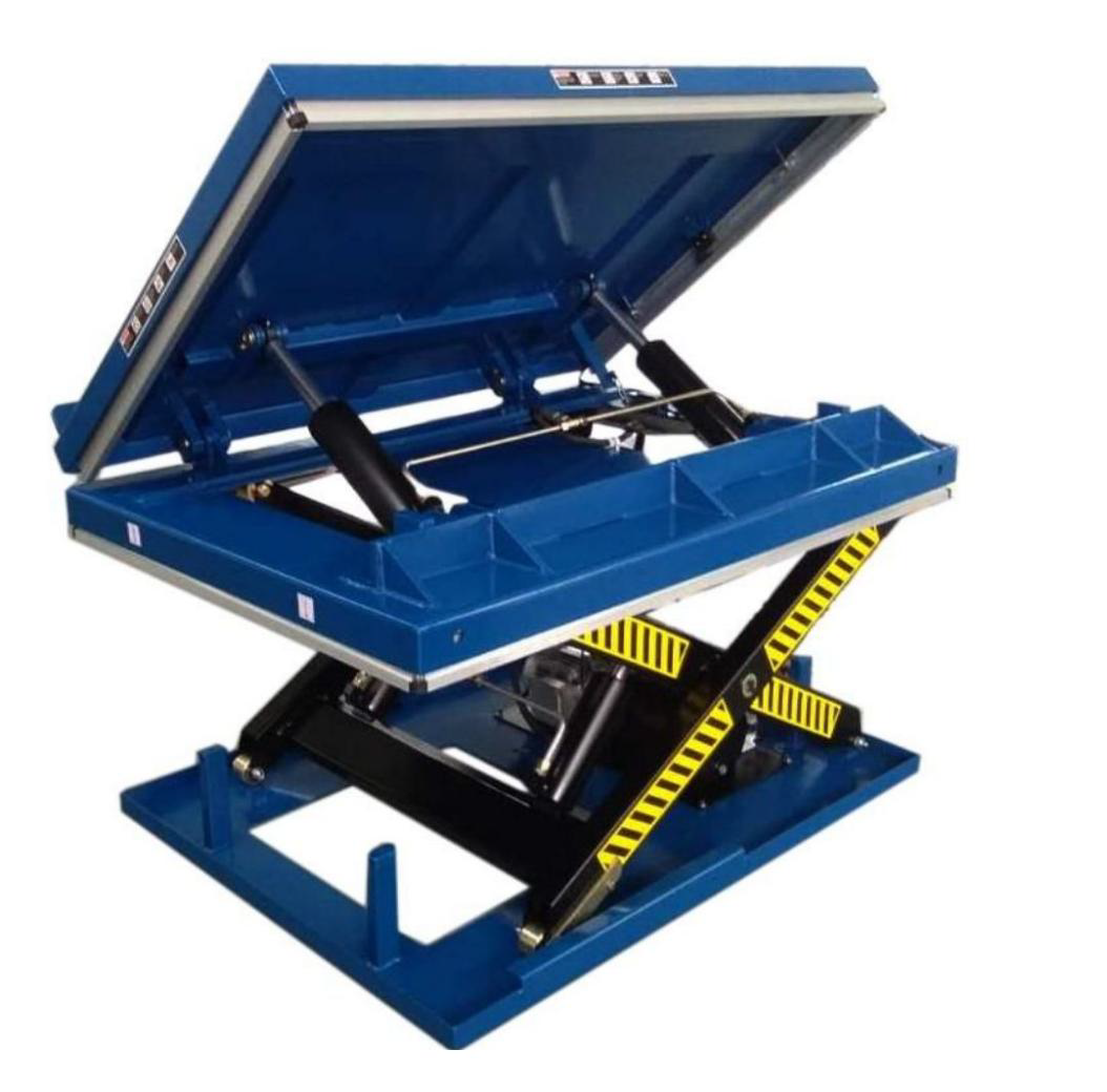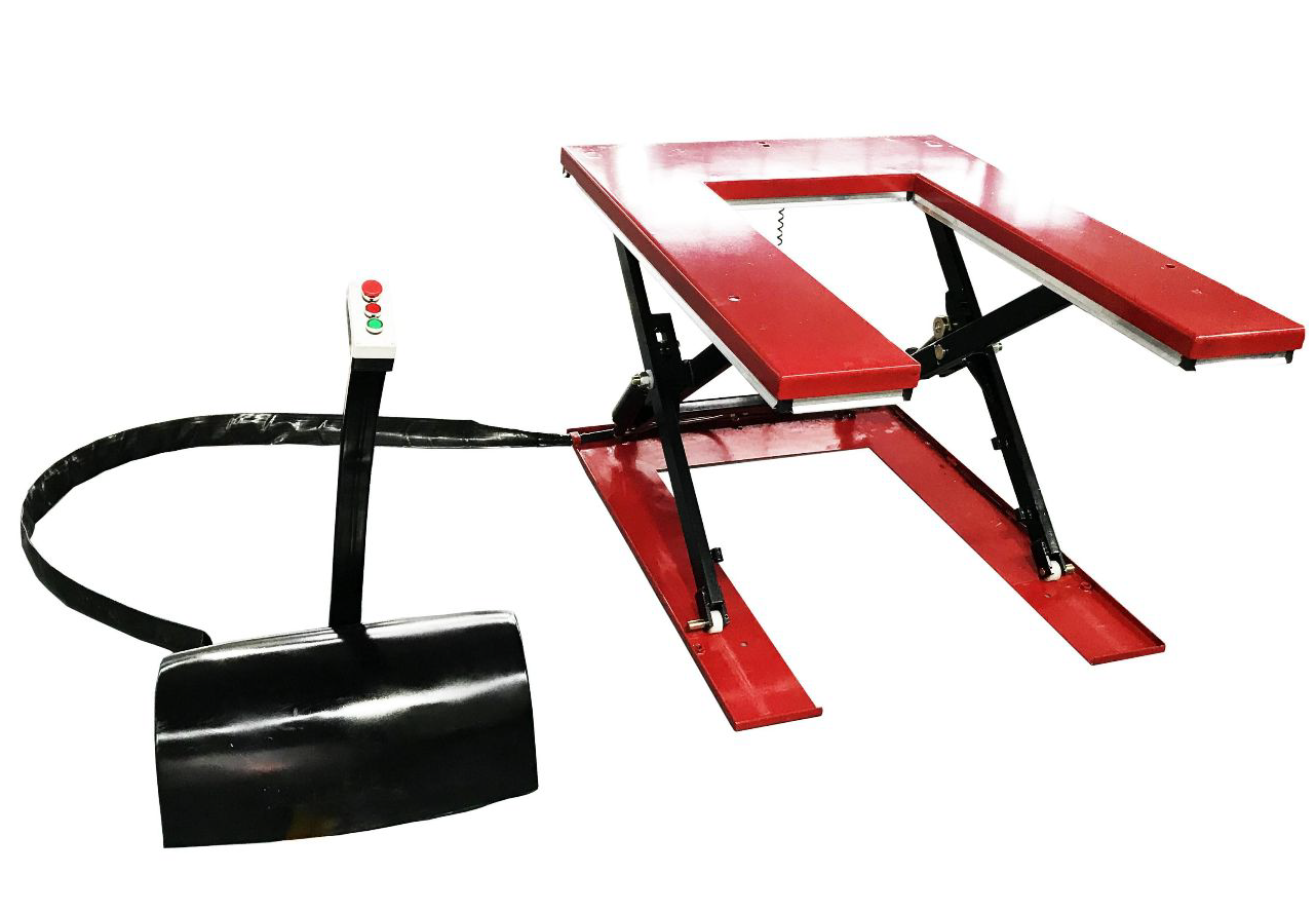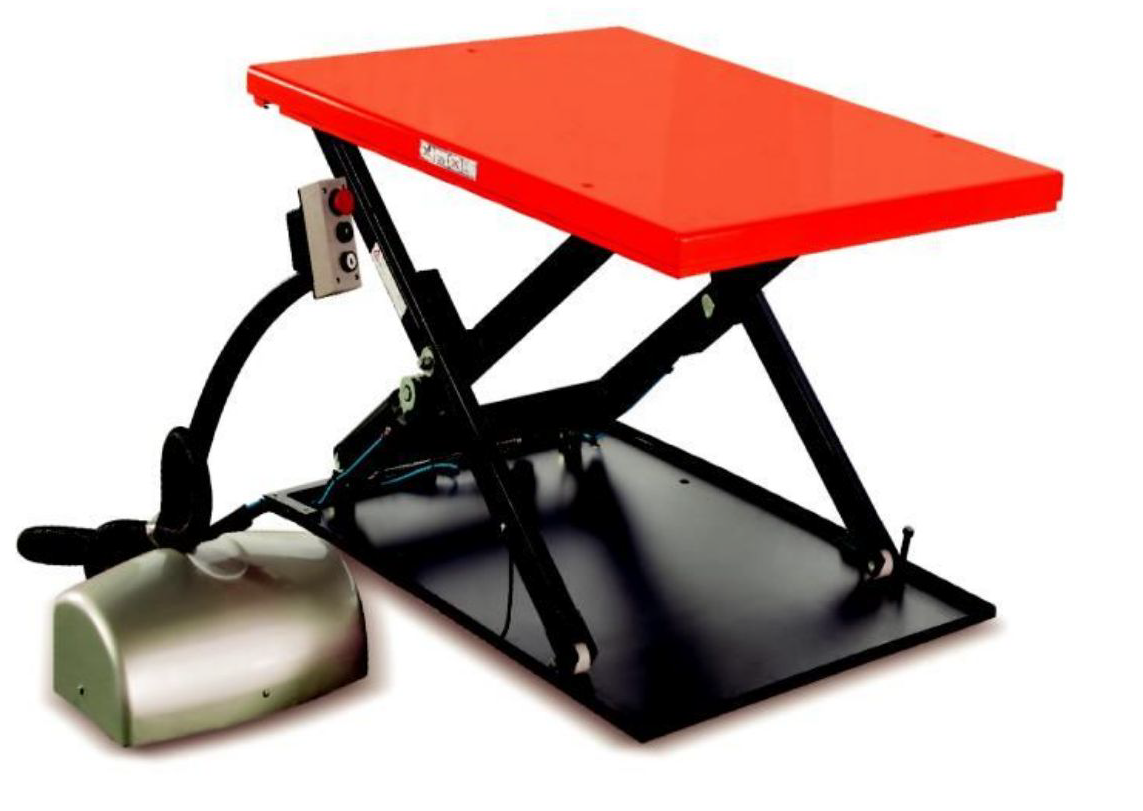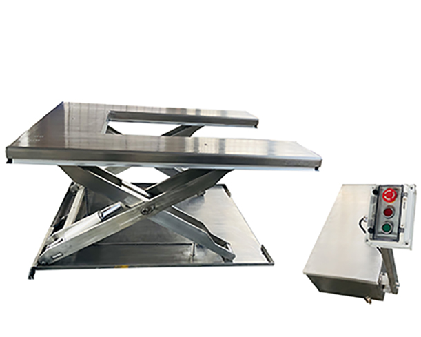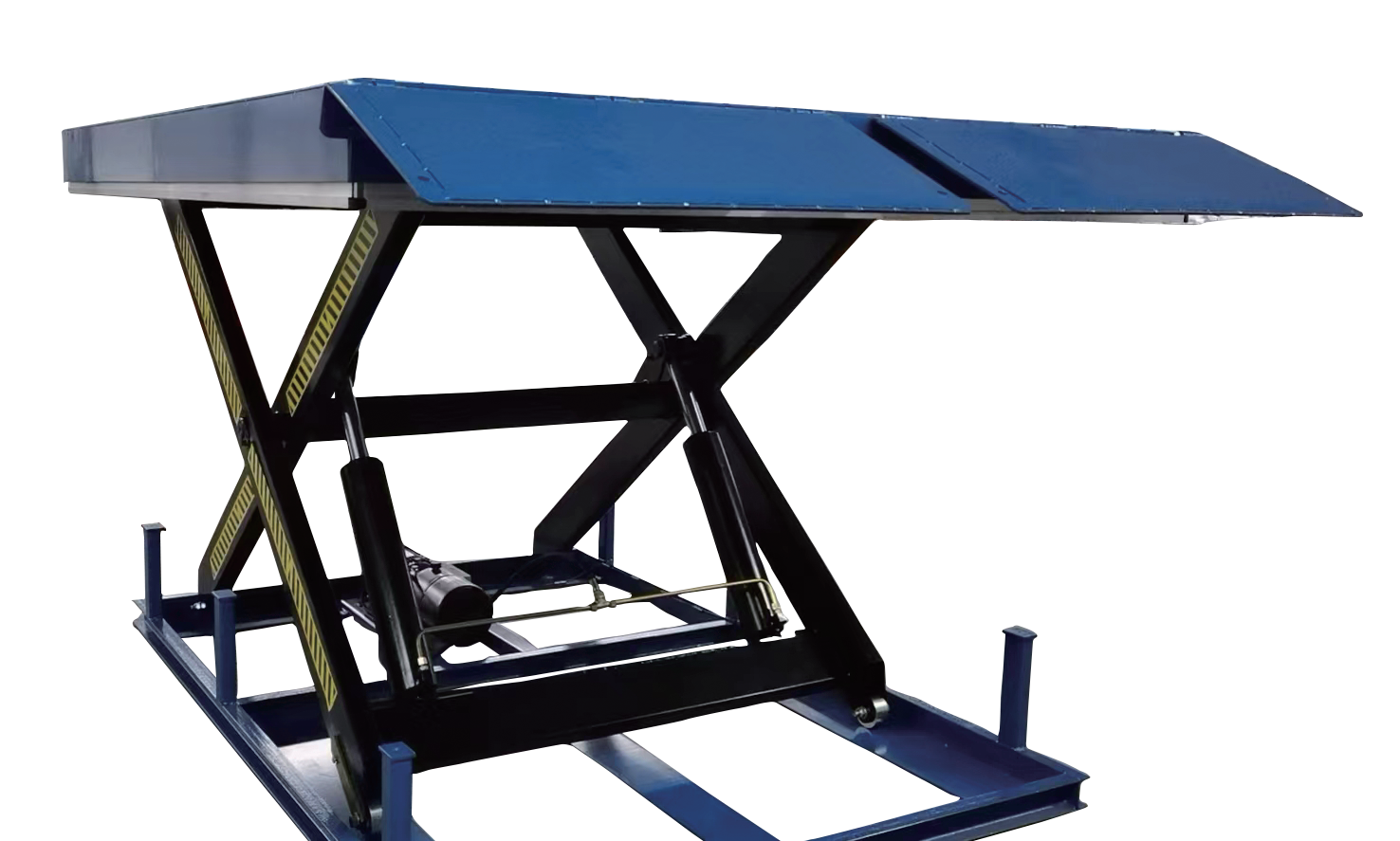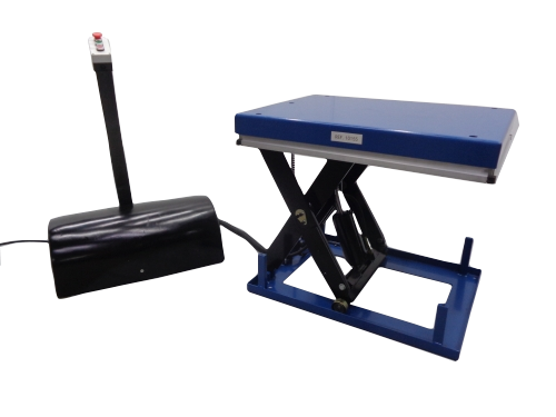
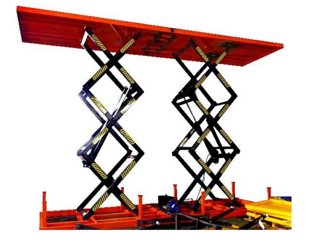
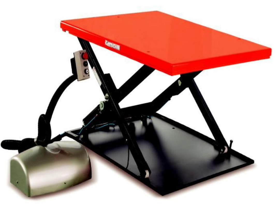
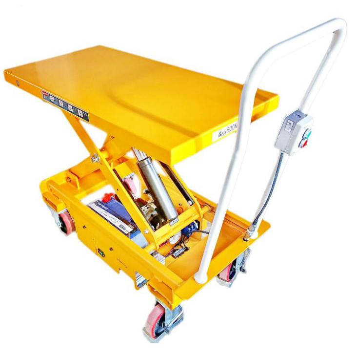
recommend products
You may also like it
NOTE: OWNER/OPERATER MUST READ AND UNDERSTAND THIS INSTRUCTION MAMUAL BEFORE USING IT.
1. GENERAL
This manual contains important information for the correct installation, operation, and maintenance of the equipment described herein. All persons involved in such installation, operation and maintenance should be thoroughly familiar with the contents of this manual. To safeguard against the possibility of property damage or personal injury follow the recommendations and instructions of this manual and keep it for further reference.
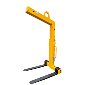
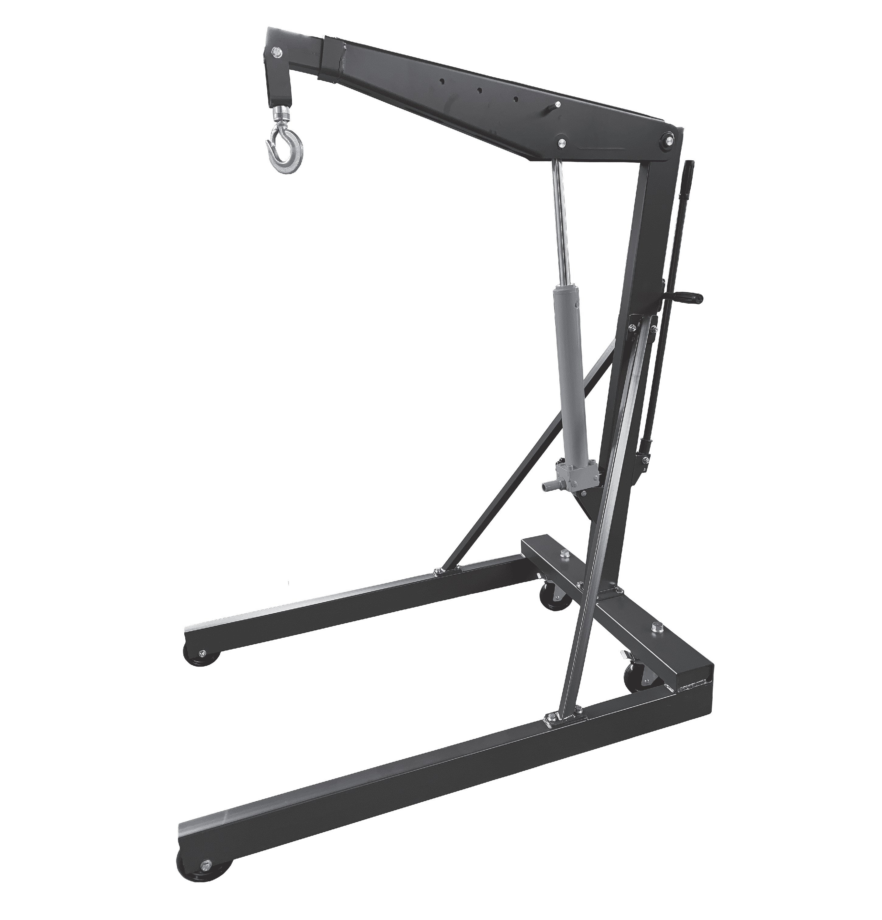
Two types of crane forks are produced as follows.
A. Crane forks with manual weight balancer, adjustable height. These crane forks are equipped with adjustable tines and height adjustability. The balancing system engages when the shackle is manually hooked into the appropriate notch.
B. Crane forks with automatic weight balancer, adjustable height. These crane forks are equipped with adjustable tines, height adjustability and an automatic balancing system.
Crane forks with automatic balancing tend to point their tines upward when being transported. This prevents the load from unintentionally slipping off the tines.
The automatic balancing system requires a minimum load of 20% of the crane fork's working load limit.
The shackle is movable and runs on a track depending on the load. The automatic balancing engages by a pressurized gas spring once the forks are loaded. The load will always be in the center of gravity of the forks, ensuring a safe transport.
All crane forks comply to the safety specifications from the German trade association, and have been manufactured in accordance with the Machinery Directive 98/37/EEC. They are type-tested 4tol against breakage. Each unit is proof-tested 1.5 times of the rated load.
They have the following features:
1. maintenance-free
2. highly visible safety color
3. for the transport of rings or coils, the fork tines are simply pushed together.
4. easily adjustable tines for all pallet sizes.
5. with chain for load securing.
2. SPECIFICATION
Model | Capacity
t | Weight
kg | Adjustable fork width A mm | Effective height B mm | Fork length C mm | Fork cross D mm | Hook height E mm |
CK10 | 1 | 128 | 350-900 | 1100-1600 | 1000 | 100×30 | 1390-1890 |
CK15 | 1.5 | 151 | 350-900 | 1300-2000 | 1000 | 100×40 | 1600-2300 |
CK20 | 2 | 198 | 400-900 | 1300-2000 | 1000 | 120×40 | 1640-2340 |
CK30 | 3 | 246 | 450-900 | 1300-2000 | 1000 | 120×50 | 1670-2370 |
CK50 | 5 | 372 | 500-1000 | 1300-2000 | 1000 | 150×60 | 1700-2400 |
CY10 | 1 | 138 | 350-900 | 1100-1600 | 1000 | 100×30 | 1420-1920 |
CY15 | 1.5 | 166 | 350-900 | 1300-2000 | 1000 | 100×40 | 1650-2350 |
CY20 | 2 | 218 | 400-900 | 1300-2000 | 1000 | 120×40 | 1655-2355 |
CY30 | 3 | 278 | 450-900 | 1300-2000 | 1000 | 120×50 | 1720-2420 |
CY50 | 5 | 382 | 500-1000 | 1300-2000 | 1000 | 150×60 | 1710-2410 |
Warning
To avoid damage and/or personal injury:
1. Do not exceed maximum load of the crane fork.
2. Do not use the crane fork to lift or transport people.
3. Do not use damaged crane fork or crane fork that is not working properly.
4. Do not lift or transport loads over people and make sure all personnel remain clear of supported load.
5. Do not apply the load to the tips of the tines.
6. Do not leave load supported by the crane fork unattended unless specific precaution have been taken.
7. Do not lift loads that are not balanced, and the holding action is not secure.
3. INSTALLATION
Estimate the weight of the load that is to be lifted or transported and make sure it does not exceed the rated load of the crane fork.
Make sure the crane or sling to which the shackle or lifting ring is attached is strong enough to hold several times of weight of the load to be lifted or moved.
Adjust the height and the tines to suit the size of the pallet or palletized box.
4. OPERATION
The crane fork has been constructed to lift and transport pallets/skeleton boxes, containers or similar. The load should be positioned equally on both fork tines and load center should be around the center of the tines.
The load is to be positioned so that there is no danger of it's overturning.
4.1 Maximum lifting capacity
The crane fork was designed to lift and transport loads up to the rated capacity. The capacity indicated on the crane fork is the maximum safe working load which must not be exceeded.
4.2 Danger zones
1. Do not lift or transport loads while personnel are in the danger zone.
2. Do not stand or place hands or feet under the raised forks.
3. Raised loads are not to be left unattended for a longer period of time.
4. The operator may only start to move the load when he is sure the load will not overturn and that all personnel have left the danger zone.
4.3 Do move the big shaft (see part list item 3) to the front hole when the crane fork is operated and the load is not balanced this means that the shaft is moved to position B"
Position A:
At the rated capacity (exceed the rated capacity 20%), the big shaft (item 3) should be put The Position A when the center of gravity of the load is inside about 450mm distances between the front fork and back fork.
Position B:
The big shaft (item 3) should be The Position B when the center of gravity of the load is not balance or at about 450~600mm distances between the front fork and back fork.
4.4 Service and maintenance
Adhering to the inspection and maintenance instructions is as much a part of the "de-fined intended use" of the crane fork as acting in accordance with the operating instructions. If faults are detected the crane fork must be put out of service immediately. To ensure that the crane fork remains in safe working order it is to be subjected to regular inspections by a competent person. Inspections are to be annual unless adverse working conditions dictate shorter periods. The components of the stacker are to be inspected for damage, wear, corrosion or other irregularities and all safety devices are to be checked for com-pleteness and effectiveness. Repairs may only be carried out by a specialist workshop that uses original spare parts.
5. EXPLODED VIEW & PART LIST
Item | Description | Qty |
1 | Sealing Plate | 1 |
2 | Screw M6 | 2 |
3 | Big Shaft | 1 |
4 | Small Shaft | 1 |
5 | Gas Spring | 1 |
6 | Nut | 1 |
7 | Nylon Roller | 6 |
8 | Retaining Ring | 2 |
9 | Shaft (for air spring) | 1 |
10 | Balancing Shackle assy. | 1 |
11 | Tine assy. | 2 |
12 | Adjustable shaft | 1 |
13 | Chain for load securing | 1 |
14 | Top frame assy. | 1 |
15 | Securing Spring | 3 |
16 | Body assy. | 1 |
17 | Screw M12 | 4 |
18 | Retaining Plate | 2 |
ADD: No.80 Kengdong, Shenjiawu Village, Yinhu Subdistrict, Fuyang District Hangzhou City, Zhejiang Province China 311404.
MOBILE TEL: 86-17348532130
EMAIL: frankd@hzshuli.com
TEL:+44 (0)7852472210


Long Press to Scan QR Code
Scan QR Code